Bulla Road Bridge North Abutment Geotechnical Design and Construction Performance of Abutment Modification
M. P. Chan, BEng/BA MIEAust and M.Y. Broise BSc (Hons)
26th November 2018
Abstract
Many civil engineering structures rely on geotechnical input to provide practical and innovative solutions, often in the face of uncertainty. In a recently completed major roadway widening project in Melbourne, a geotechnical alternative design was proposed to modify an existing bridge spill-through abutment to improve the functionality of the roadway by enabling the construction of two traffic lanes rather than a single lane proposed in the reference design. The solution involved removing the spill-through abutment and slicing through the counterfort buttress retaining wall and its foundations to form a continuous vertical face, transforming the retention system into a monolithic blade wall laterally supported by soil nails and rock bolts. This paper describes the alternative solution that was adopted and identifies the construction risks that had to be managed during construction. The importance of real-time and continuous geotechnical monitoring as a means to control the excavation sequence and verify abutment performance throughout the construction works is emphasised. Keywords: Abutment stabilisation, geotechnical risks, soil and rock nails, instrumentation and monitoring.
Keywords: Abutment stabilisation, geotechnical risks, soil and rock nails, instrumentation and monitoring.
1. Introduction
The Tullamarine Freeway (Tulla) is the major urban roadway linking Melbourne Airport to Melbourne City. The Tulla received an upgrade in the late 1990’s between Flemington and Bulla Road Bridge, which is at the southern end of Essendon Airport, by the construction of Western Link of CityLink.
During the tender design of the recently completed further upgrade the joint designers posed the question how could the existing freeway carriageway at the toe of a spill-through abutment be widened to improve the geometric alignment and functionality of the roadway to enable a two lane collector distributor carriageway to be constructed beneath the northern abutment of the existing Bulla Road Bridge.
Constraints with respect to right-of-way boundaries, existing bridge piers, and the imposed condition of no disruption to bridge traffic eliminated any opportunities of major realignment work, bridge lengthening, structural modifications or the construction of a new separate retaining wall. The requirement to upgrade pier protection barriers for traffic collision loads also reduced the space available to accommodate other possible options such as slope regrading with or without toe shear keys.
The adopted solution was based on modifications carried out in the 1960’s to one of I.K.Brunel’s heritage listed steel bridges in the United Kingdom.
2 Background
2.1 Subsurface Profile
The bridge site (see Figure 1) is located on Quaternary age Newer Volcanics Basalt terrain which forms an undulating plateau. The Tullamarine Freeway at this location is in a 7 m deep cutting.
The Newer Volcanics typically comprises a capping of highly reactive residual basaltic clay overlying weathered basalt rock at variable depths. Floaters of sound rock are often embedded in the clay profile.
The clay-rock interface is characteristically irregular over short distances hence the lateral conditions can vary abruptly from clay to rock. In addition, the top of rock can exhibit a transition zone grading from loosely jointed blocks surrounded by soil or extremely weathered material into a near continuous rock mass with weathered products confined mainly to the network of discontinuities.
The discontinuity pattern in basalt can be complex, including vertical polygonal columnar joints together with a series of sub-horizontal joints often related to multiple flow boundaries, and curvilinear spheroidal joints that develop around the perimeter of corestones. Clay coated vertical to sub-vertical joints are common. From the available vertically drilled borehole records it was not possible to fully define the rock mass jointing system.
The regional groundwater table was well below carriageway level and thus of no influence.
Historic borehole logs described the subsurface conditions as mainly clayey fill, over basalt with decomposed layers and honeycomb bands. The ground profile revealed by the nearest project-specific borehole drilled behind the north abutment is shown in Figure 2.
Gravel fill was encountered to about 2.7 m depth, over clay to 3.8 m, underlain by basalt with weathering grades of Highly weathered (HW), Moderately Weathered (MW), and Moderately to Slightly Weathered (MW-SW). The Rock-quality designation (RQD) in the basalt varied between 41% and 91% in the upper profile reducing to 0% to 55% below about 8.5 m depth.
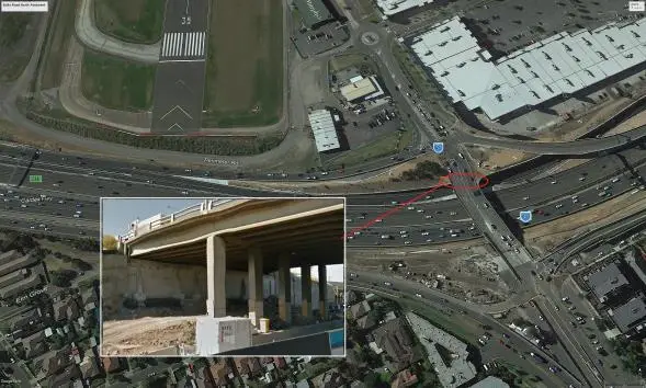
Figure 1. Bulla Road bridge north abutment location
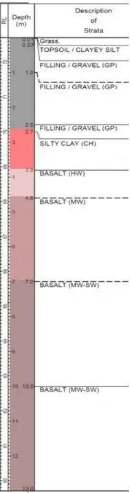
Figure 2. Ground profile behind north abutment
2.2 Existing Bridge & Abutment Structure
The 4 span bridge superstructure is a cast-in-situ concrete deck over pre-tensioned I-girders that are continuous over the piers. Each pier has five columns that are supported by a pad footing founded on weathered basalt.
The abutment is formed by a sill beam supported by seven (3 m high) reinforced concrete counterfort buttresses on individual spread footings founded on weathered basalt about halfway up the spill-through batter.
Because the superstructure is fixed at each pier and simply supported on sliding bearings at the abutments, the abutment did not need to be designed for longitudinal loads which are transmitted to the adjacent pier.
Also, there is no approach slab at the north abutment, which raised some uncertainty with respect to the behaviour of the fill behind the abutment possibly creating additional lateral earth loads over time.
3 Risks & Major Constraints
While the available information was sufficient to generally establish the ground profile and broad properties of the materials, there was insufficient knowledge as to the likely occurrence of geological features (i.e. lateral variation in weathering, influence of joint sets) that could adversely impact design and construction. In face of such uncertainty a qualitative risk assessment was undertaken to test the robustness of the design to different but credible scenarios and devise preliminary construction mitigation measures in anticipation of unfavourable conditions.
The main geotechnical risks that were identified and needed to be addressed are listed in Table 1.

The works had to be performed out under live traffic conditions from the bridge above and the adjacent existing carriageways which carry a high volume of traffic.
As the proposed construction methods would involve percussive drilling and bulk excavation in rock there was the potential to affect the structural integrity of the bridge, stability of the temporary cutting, and nearby underground assets deemed to be movement sensitive. Accordingly, recommended levels of maximum ground vibration were set to reduce the likelihood of damage caused by induced ground borne vibrations.
With regard to deflections of the bridge abutment the designers specified a maximum allowable lateral movement of 10 mm together with a maximum settlement of 5 mm. Although it was understood that greater movement could be accommodated by the structure. These limits were cautiously established to
ensure that any increase in moments and forces would be well within the existing capacity of the superstructure, obviating the need to carry out any strengthening works (Patoary and Nguyen, 2017).
4 Geotechnical Design Solution
4.1 Source of Inspiration
The concept for abutment modification was inspired by a method used for cliff face strengthening during reconstruction of I.K.Brunel’s tubular railway bridge at Chepstow over the River Wye in the United Kingdom, as described in ”The Girder Bridge” (Berridge 1969).
During the 1962 reconstruction Brunel’s original tubular trusses superstructure was replaced with new steel underslung trusses below the existing deck at the river span. In order to improve stability of the sub-horizontally bedded carboniferous limestone cliff at the abutment, the rock face was anchored into the body of the slope. The main geological defect was identified to be persistent sub-vertical discontinuities which had developed a zone of opened joints through the rock mass due to stress relief caused by erosion and river undercutting. While such valley structures are commonly related to gravitation stress relief generated in post periglacial times, particularly involving sedimentary rocks, the general instability mechanism can be equally applied to other geological environments anthropogenically modified.
At Chepstow, forty 19 mm high tensile steel expanded shell “Bayliss” rock bolts were installed in 42 mm diameter drilled holes extending between 9 m and 12 m in length into the cliff face at a downwards inclination of 5 degrees. The bolts had a nominal vertical and horizontal spacing of 1.5 m.
4.2 Solution Adopted
The alternative design at Bulla Road Bridge involved removing the existing spill-through abutment and literally slicing through the buttress retaining wall spread foundations at mid-slope height to form a vertical face down to the final carriageway level to create the necessary formation width for two traffic lanes between the abutment and adjacent pier.
To provide lateral retention against earth and surcharge pressures, ground retention was achieved using a combination of soil nails above the abutment footing and tensioned rock bolts beneath the base of the abutment footing. The general arrangement of the abutment modification is shown in Figure 3.
A new blade wall and a continuous strip footing connecting the existing spread footings were formed to transfer and resist the axial loads from the abutment. The width of the new wall is similar to the thickness of the existing footing column.
The abutment wall consisted of seven rows of permanent anchorages. The three upper rows were 8 m long soil nails and 25 mm diameter galvanised threaded bars encapsulated in a corrugated HDPE sheath. These were expected to be installed through soil and rock or a combination thereof. Rows 4, 5, 6, and 7 consisted of double corrosion protection (DCP) expanded shell rock bolts, initially tensioned via the expansion head prior to final grouting. The advantage of using this bolt type is the ability to apply nominal end fixity to counteract potential loosening or opening of joints within the stressed block. However, an expanded shell relies on being securely wedged against the rock interface to provide resistance. Bolt layout was on a staggered pattern with a horizontal and vertical spacing of 1.2 m and 1.0 m respectively. Physical properties for the bolts are given in Table 2.

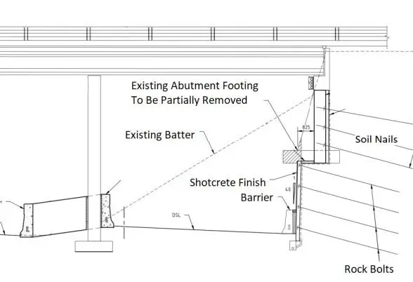
Figure 3. General arrangement of abutment retention
4.3 Numerical Modelling
To comply with the Project Scope & Requirements the design had to satisfy the general principles of geotechnical design of strength (overall stability) and serviceability.
The computer program STARES was used to assess the stability of the soil/rock mass and determine the soil nail and rock bolt layout. The program analyses earth slopes stabilised by internal reinforcement using Bishop’s simplified moment equilibrium method of slices for unreinforced slopes.
Although the program is formulated to analyse “c-ø” soils based on the Mohr-Coulomb failure criterion along circular failures surfaces it was considered generally appropriate in this case to simulate a highly decomposed rock mass which could behave similar to a cohesive granular material in the most unfavourable conceivable condition. The modelling parameters are given in Table 3.

A surface surcharge of 60 kPa was included to simulate the backfill pressure. A factor of safety of 2 was applied to the ground-to-grout adhesion to minimise potential creep movement developing in circumstances of unforeseen overloading. Stability was also checked for seismic loading.
For the design of serviceability the finite element (FE) software program RS2 developed by Rocscience was used to predict overall deflections and face earth pressures for structural design of the wall. RS2 is suited to analysing soil and rock slopes using various failure criteria and joint network systems to simulate the effects of the defect patterns within a rock mass.
The modelling indicated that in order to limit the abutment movement to within the permissible target levels, the rock bolts below the footing were required to be pre-tensioned to a nominal value of 50 kN.
5 Construction Methodology
The following tightly controlled construction sequence was developed to manage the range of risks that had been identified during workshops.
Firstly, the batter was trimmed to allow for machinery access. Each bench was then excavated in divided bays using a “hit and miss two” sequence to enable the installation, grouting and nominal stressing across each single row of retention and shotcreting. The sequential method is shown in Figure 4 which is a full height elevation of the north abutment, illustrating the I-girders, the counterfort buttresses and level of the modified abutment footing.
The principal objective of the sequential pattern was to utilise the arching effects between the left in place intervening buttresses to support sections of the excavated faces until such time that the nailed retention took effect.
Once the excavation and nailed installation reached the underside of the spread footings, the wall was stitched together to form a continuous blade wall. When completed the toe of each pad footing was saw-cut to the required set back.
Excavation and face trimming continued below the spread footing into the weathered basalt rock mass. The hit and miss sequence was continued using an excavator mounted twin head rock grinder, a low vibration method of rock extraction. See photo 1.
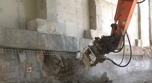
Photo 1. Rock face cutting below new continuous footing and saw cut buttresses.
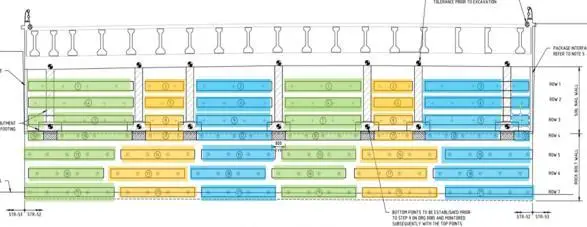
Figure 5: Lateral soil movement in IPI at 1.5 m depth
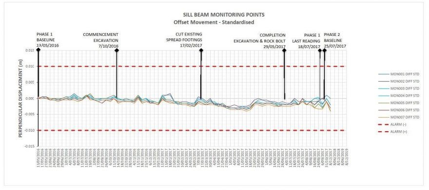
Figure 6: Abutment sill beam monitoring results (standardised)
8 Conclusion
A geotechnical design alternative was proposed to modify an existing bridge spill-through abutment to improve roadway geometry and its functionality by enabling two lanes to be constructed rather than a single lane in the reference design.
The solution involved removing the spill-through abutment and slicing through the counterfort buttress retaining wall foundations to form a continuous vertical face and transform the retention system into a monolithic blade wall. Works were carried out under live traffic crossing the bridge above.
The works were classified as high risk, which necessitated a collaborative approach between the design and construction teams to develop a practical construction methodology that satisfied all aspects of safety in design.
A combination of soil nails and rock bolts were used to stabilise the abutment excavation and foundations. A “hit and miss two” sequence was used to control the cut face stability and abutment deflections by limiting the extent of disturbance caused by the excavation. Data from a detailed monitoring programme confirmed that the performance of the modification works was within the prescribed tolerance limits for the structure.
The close collaboration between geotechnical engineers and the construction team resulted in timely resolution of inevitable deviations that arose during construction.
The new widened carriageway beneath the bridge was opened to traffic in 2017.
9 Acknowledgements
The authors acknowledge the following project team members, end client and main contractor in contributing to a successful outcome.
- CPB Contractors
- Aurecon GHD Joint Venture
- Transurban
- VicRoads
References
Berridge, P.S A. (1969). “The Girder Bridge after Brunel and Others”. Robert Maxwell Publisher, London, 172pp.
Patoary,K., Nguyen, A. (2017). “CityLink Tulla Widening – Existing Bulla Road Bridge North Abutment Modification. 8th Australian Small Bridges Conference.
RS2 Soil and Rock Finite Element Analysis software program by Rocscience.
STARES Balaam, N.P. (1999). “Stability Analysis of Reinforced Soil”. Centre of Geotechnical Research, University of Sydney, N.S.W.
Download the PDF here.
Chan-P.-Geotechnical-Design-and-Construction-Performance-of-Abutment-M