Abstract
This paper describes the design of embankments and piled foundations for new bridges across Moonee Ponds Creek as part of the Melbourne M80 Upgrade Project. The bridges are part of the eastbound duplication and consist of 7 spans (main carriageway) and 8 spans (auxiliary exit). The maximum approach embankment height relative to the existing ground surface levels is 17 m, which is up to 6.5 m higher than the adjacent embankment. Moonee Ponds Creek transects the Newer Volcanics and Melbourne Mudstone forming an incised valley (Moonee Ponds Creek Valley) filled with Quaternary alluvial deposits. Significant settlement was experienced during the construction of the original embankments in the early 1990s. The specification for the new bridges imposed tight settlement requirements. This challenge was compounded by restricted space between assets and a tight construction time frame.
Details of the construction methodology together with the results of settlement monitoring and the monitoring of vibration due to impact rolling and pile driving are presented.
1. Introduction
Construction of the M80, which was originally known as the Western Ring Road, began in 1989 and was completed mainly in three sections by June 1997. The section between the Tullamarine Freeway and Pascoe Vale Road that also included a bridge over Moonee Ponds Creek (MPC) was completed in September 1992.
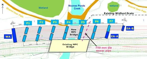
The eastbound duplication of the existing carriageway between the Tullamarine Freeway and Sydney Road (the former Hume Highway) which included the Moonee Ponds Creek Bridges amongst others, was undertaken between 2009 and 2012 by means of an alliance partnership between VicRoads, Thiess, Parsons Brinckerhoff (PB) and Hyder. Douglas Partners (DP) was requested to provide geotechnical design services to the Alliance. The construction of the bridges over Moonee Ponds Creek was completed by the end of 2011. The approximate location of the bridges is illustrated in Figure 1.

2. Design Criteria and Site Constraints
The “Alliance Project Specifications” detailed certain performance criteria for the new widening. There were also some site constraints that had to be taken into account at the design and construction stages. The major design criteria and site constraints were:
- The maximum freeway longitudinal grade to be 4%;
- The new bridge structures should not impose any additional loads on or otherwise impact on the existing bridge;
- The maximum settlement in the measured earthwork and pavement surfaces at the end of the Defects Liability Period was not to exceed a differential settlement of 20 mm over a distance of 5 m within 20 m of the abutments. The estimated gross settlement including creep (extrapolated on a logarithmic time scale from measured settlements) at any point in the earthworks and pavement was not to exceed 50 mm over a period of 10 years following the date of Practical Completion. (In comparison, settlement monitoring at the 9 m high west abutment of the original M80 recorded a total settlement of about 270 mm over 1 year including the embankment construction of 3 months);
- The available space for the construction of the duplication was limited by the presence of a 1.5 m diameter major stormwater drain (Widford Drain) along the northern toe of the existing east embankment. Melbourne Water, the owner of this asset, required the drain not to be buried further by the new embankment and that construction vibrations were not exceed 10 mm/sec;
- A deep 750 mm diameter sewer pipe parallel to MPC. Yarra Valley Water, the asset owner agreed a construction vibration of 25 mm/s and
- The presence of a wetland reserve towards the north of the embankments.
3. Ground Conditions
Moonee Ponds Creek transects basalt of the Quaternary Newer Volcanics and Melbourne Mudstone basement, forming a broad valley filled with Quaternary alluvial deposits.
Site investigation was carried out during the M80 construction in the late 1980’s (VicRoads, 1989). Additional drilling as required by AS5100, consisting of one borehole at each abutment and pier, was undertaken by the Alliance for the widening in 2009-2011. In addition, Cone Penetration Tests (CPTs) were conducted at the abutment and pier locations of the new bridges. The detailed ground section is given in Figure 2.
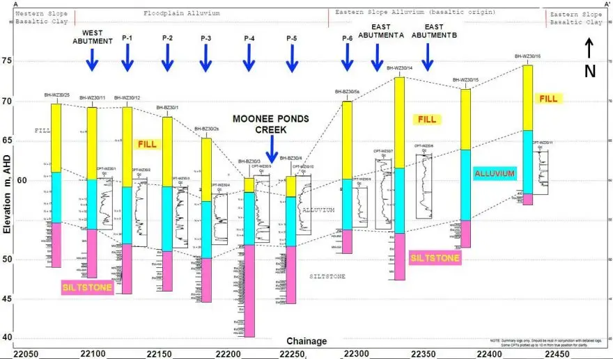
The investigation (Douglas, 2010) revealed that the ground conditions consisted of up to 8.5 m thickness of existing embankment fill placed over up to 8 m of typical floodplain alluvium at the middle to western section of the valley. Alluvium of basaltic origin covered slopes on the higher elevations of the valley. Both types of alluvial deposits were predominantly underlain by siltstones/sandstones in the valley floor.
The investigation showed that the embankment core comprised compacted engineered clay fill with side batters of 1V:1.5H. Outside of the core zone, the filling was assessed as being generally uncontrolled and consisting of a mixture of rock and clay, with some boulders having a size in excess of 500 mm.
The floodplain alluvium generally comprised firm to stiff silty clay overlying medium dense clayey sand or sandy gravel and was typically characterised by lenses of loose sand and pockets of soft clay. The gentler eastern slope of the valley consisted of alluvial clay of basaltic origin. A limited extent of fissured basaltic alluvium was also found on the steeper western slope next to the hillside. This alluvium consisted of stiff to very stiff, grey-brown, high plasticity silty clay with a trace of siliceous gravel.
4. Design Concept
From an economic perspective, the use of earthen embankments was preferred over a viaduct type structure.
To achieve the required freeway grade, the new carriageway had to be raised in relation to the existing carriageway. To satisfy the requirement of no impact of the new bridge structures on the existing bridge and wetlands, the selected solution was to make the new bridges longer than the existing bridge. It was decided to adopt two multi-span bridge structures of different lengths immediately adjacent to each other (see Figure 3).
To stay within the construction boundaries, the new carriageway had to be located close to the existing carriageway, which required a vertical wall between the two to allow for the change of level. This was achieved by adopting a mechanically stabilised earth (MSE) wall for the southern side of the new carriageway. The overall batter slope on the northern side of the new carriageway was set at 1V:2.5H and 1V:3H for the eastern and western embankment respectively.
Driven 350 mm square precast concrete piles terminating in the siltstone/sandstone rock were selected for the bridge foundation purely on the basis of being the most economical foundation option, especially given the ease by which capacity verification could be undertaken. However, an issue for this pile type was the possible presence of boulders within the existing embankment fill.
5. Geotechnical Properties
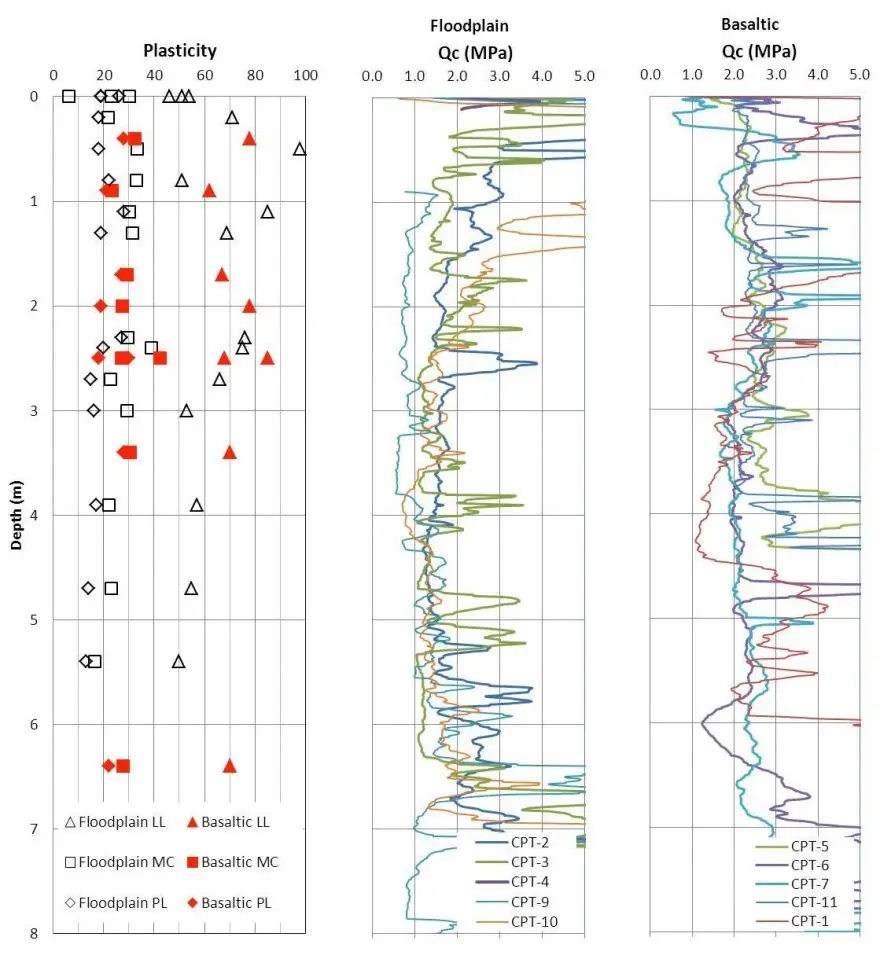
CPT probing showed the strength consistency of the alluvium within the floodplain gradually changed between firm and stiff from the ground surface and transitioned to the very stiff residual basaltic clay at the western end, whereas the basaltic alluvium was very stiff. The basaltic clay on the eastern end of the site was very stiff to hard. Figure 4 provides a summary of the material properties of the floodplain and basaltic alluvium.
Settlement monitoring at the 9 m high west abutment of the original M80, founded on the floodplain alluvium, recorded a total settlement of about 270 mm over 1 year of which 180 mm settlement was recorded post construction (9 months). The corresponding back calculated coefficient of consolidation, cv was about 30 m2/year. The laboratory consolidation test results indicated that the floodplain alluvium and basaltic alluvium were normally and slightly overconsolidated respectively.
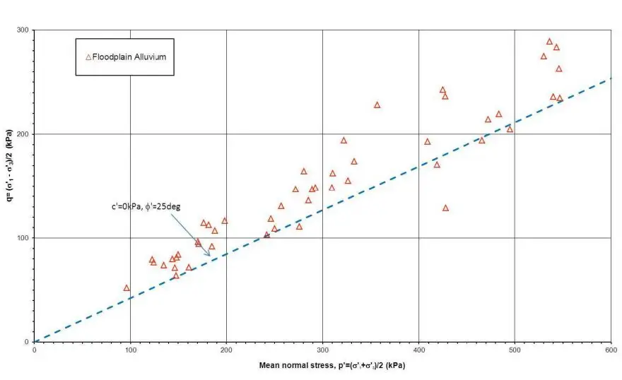
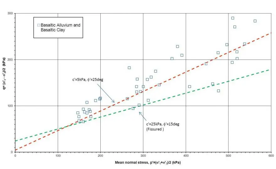
The overconsolidated basaltic alluvium and basaltic clay would be expected to exhibit some degree of effective cohesion whereas the floodplain alluvium in the middle and to the west of the creek was normally consolidated and hence less cohesion was expected, as shown in the triaxial test results (Figures 5a & 5b).
For the floodplain alluvium, shear strength parameters of c’=0 kPa and φ’=25° were adopted (Figure 5a). Due to the potential of fissures being present in basaltic alluvial clay, a bilinear shear strength envelope defined by c’=5 kPa and φ’=25° below p’=150 kPa and c’=25 kPa and φ’=15° above p’=150 kPa were adopted (Figure 5b).
6. Embankment Construction
To keep the post construction settlement to an acceptable level, the most cost effective method was to remove the existing uncontrolled side slope fill in the existing embankments and to re-use it as controlled fill. About 2 m of uncontrolled fill was, however, left in place and compacted using impact rolling. Other than the areas behind the abutments and wing walls which were formed with structural filling and the piling zone where the maximum particle size was limited to 75 mm size, material up to a maximum particle size of 400 mm was allowed. A placement method specification was developed and used for compaction control.
The west embankment was constructed first followed by the east embankment. Both embankments were built to their full heights except for the piling platform area around the abutments, allowing primary consolidation settlement of alluvium to take place to an acceptable level, i.e. preloading. The embankment fill rate was about 1 m height per week and the total design preload time was 2 months.
After removing the uncontrolled fill, the construction of the west embankment started in November 2009 and reached the final preload height in early March 2010. The east abutment embankment started in March 2010 following completion of the uncontrolled fill removal and impact rolling, and reached the preload height in July 2010.
The east embankment construction was divided into 2 phases due to the requirement for construction of the mechanical stabilised earth (MSE) structure between the old and new carriageways. The off-ramp (auxiliary lane) abutment was completed early to allow traffic diversion, and to make room for the MSE construction.
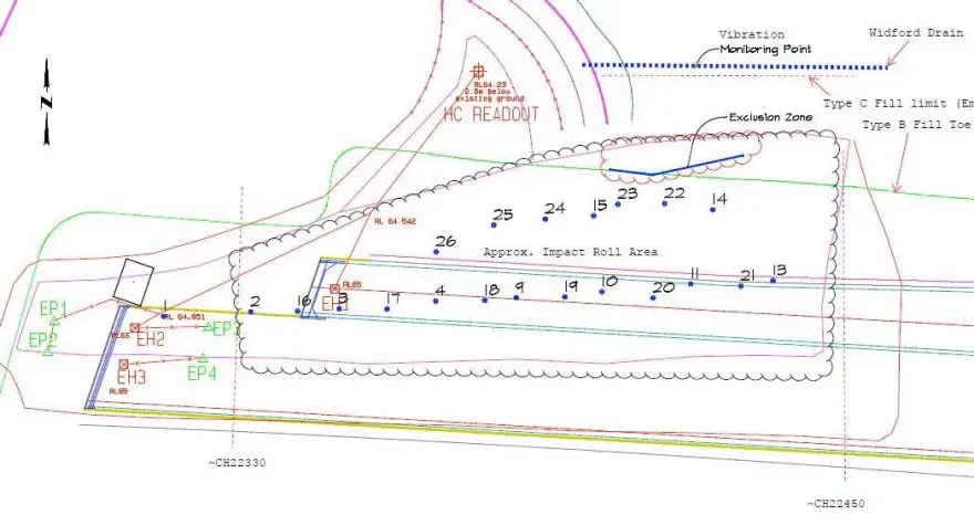
Impact rolling was carried out over two areas of the embankment footprint using a towed 3 sided high energy impact compactor. Only a plan of area Lot E1 close to the east abutment is presented in this paper as shown in Figure 6.
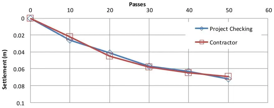
An independent level survey was carried out across the compacted area after every 10 passes to compare with those from the contractor. Up to 50 passes were completed and an average total settlement of 75 mm was achieved in Lot E1 as shown in Figure 7. Less than 10 mm of settlement in each of the last two consecutive 10 passes was recorded indicating optimum compaction has been reached. The effect of impact rolling on the compaction of the materials was qualitatively assessed by test pitting both prior and post compaction.
To manage the project risks in terms of embankment stability during construction and satisfying the settlement criteria, settlement monitoring and pore pressure measurement were implemented to provide early indications of any changes required to ensure the performance of the embankment approaches. Vibration monitoring for impact rolling was also carried out at the Widford Drain location during construction.
6.1 Vibration Due To Impact Rolling
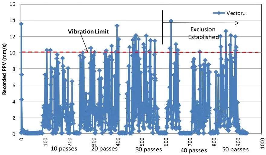
The stormwater drain (Widford Drain) owned and maintained by Melbourne Water along the northern toe of the existing east embankment is critical to the drainage of a large residential estate. Machinery induced vibration was monitored at the drain particularly for the impact rolling of the lower 2 m depth of uncontrolled fill. Melbourne Water required a Peak Particle Velocity (PPV) of not more than 10 mm/sec at the drain.
The monitoring was carried out using surface mount geophones with a BLASTRONIC µMX monitor. The results (Figure 8) showed that the vibration levels generally increased with the number of passes as the material became denser. An exclusion zone was progressively delineated as the compaction level increased to ensure that the vibrations at the drain were kept to within the defined limits. Peak vibration levels (14 mm/s max) were identified as being caused by the roller compactor directly hitting boulders within the fill but were deemed to be acceptable due to their ‘one off’ nature.
6.2 Embankment Settlement
The embankment monitoring instrumentation included hydraulic settlement cells, piezometers and inclinometers (Figure 9). Settlement survey pegs were also established at the existing abutments to assess the impact of the new embankments.
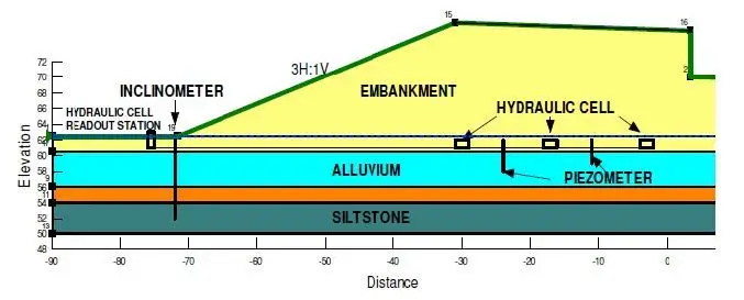
The settlement cells and piezometers were installed in the abutment areas. The results of settlement at the east abutment are presented in Figure 10. The total recorded settlement at the east abutment was about 90 mm vertically and 15 mm laterally.
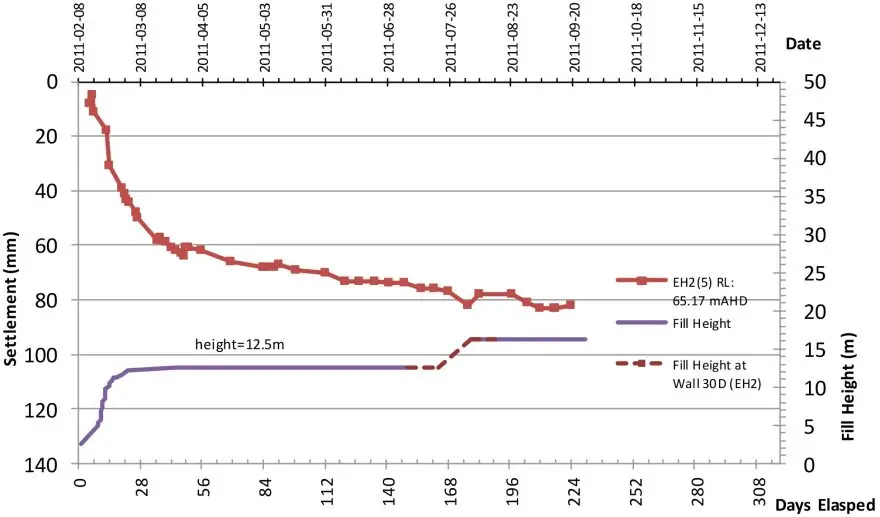
Primary consolidation of the alluvium appeared to have been largely completed after about 2 months of preloading, with the settlement flattening out on a log time scale. Preloading survey points installed on top of the embankment showed a similar stabilising trend. No significant pore pressure build-up was measured during the embankment construction. The low pore pressure is consistent with the high cv value indicated by the interpreted behaviour of the original embankment.
From the slope of the settlement plotted on log time scale, a creep rate of 40 mm per 10 years was estimated which corresponds to a secondary compression index, c of 0.004. This indicated that the embankment would meet the project specification.
7. Bridge Foundation System
The bridge foundation system comprised groups of driven 350 mm square precast concrete piles for each abutment and pier (Douglas, 2010b).
The maximum ultimate limit state axial compression load, N* was in the order of 2000 kN with no tension force on any pile. For the piles to achieve the required capacity, they were designed to be installed through new fill and alluvium and founded in variably weathered siltstone/sandstone.
7.1 Pile Design
A limit state design method was adopted in accordance with VicRoads Technical Note No. 96/001, June 2005.
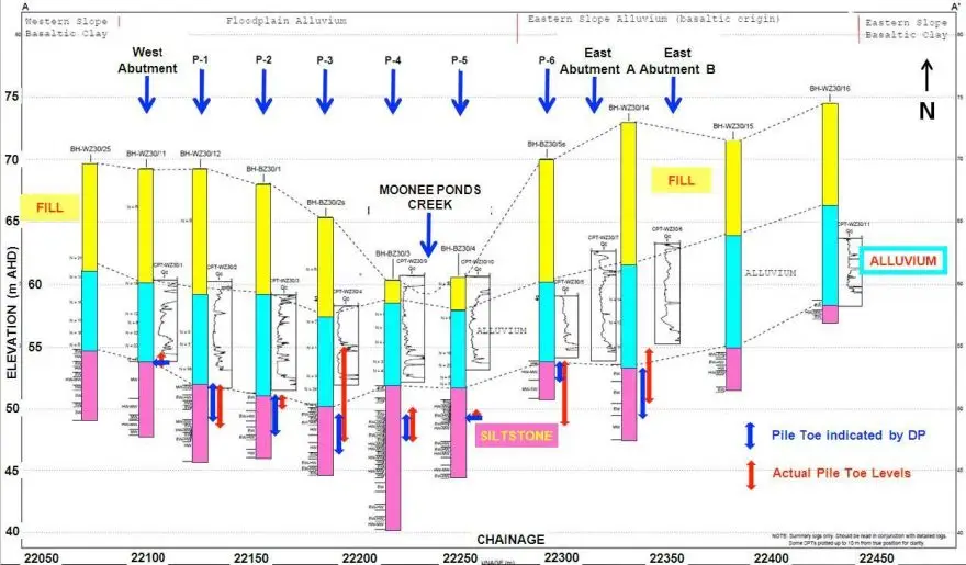
Due to the presence of deep filling and soft ground, the potential for negative skin friction (NSF) needed to be considered. Additionally, VicRoads requirements state that pile joints have to be located no closer to the final ground surface than 5 m. This required accurate estimation of the final pile toe levels. The recorded pile toe levels were within the ranges predicted by DP at the design stage (Figure 11) except for Pier 3 where early refusal believed to be due to stronger rock occurred on the northern side of the pier. The piles all reached refusal shortly after encountering low to medium strength rock.
There was early concern that pile driving through the existing fill would encounter boulders. This could have caused either premature refusal of the pile or possible deviation off line. To avoid this problem, predrilling was undertaken at all pile locations where fill was present. Predrilling was carried out using a drill size larger than the diagonal dimension of the pile (i.e. 500 mm diameter hole for a 350 mm square pile). On site, the predrilling was extended sufficiently to ensure that natural materials were encountered. The predrilled holes were backfilled with loose sand so that appropriate lateral support was provided to the piles after installation.
As well as adopting the conventional capacity verification acceptance criteria, a second criterion was imposed to ensure that the possible impacts of soil creep (including negative skin friction) were minimal. This required the ultimate soil resistance between the settling layers to be satisfied:
Φg Rug.st > (PE + NSF) (1)
Where Rug.st was the calculated ultimate pile resistance below the settling layer and PE and NSF were the unfactored permanent effect loads and negative skin friction loads respectively.
Capacity verification undertaken on about 20% of the piles at each pier/abutment location successfully proved the acceptance criteria.
7.3 Vibration Monitoring
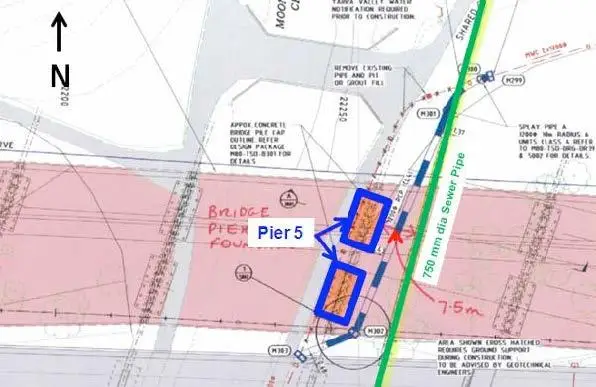
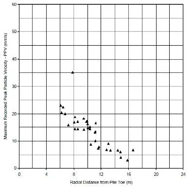
A 750 mm diameter concrete sewer pipe runs north-south along the eastern edge of Moonee Ponds Creek approximately 7.7 m below the ground surface level and at a minimum distance of about 7.5 m from the nearest pier pile cap. The location of the relevant pier and sewer is shown in Figure 12.
Vibration monitoring during the piling works at Pier 5 was undertaken to ensure that the vibration level experienced at the sewer during pile driving was less than the Peak Particle Velocity (PPV) limit agreed with Yarra Valley Water. Yarra Valley Water required that the piling caused no damage to the pipe and that piling vibration did not exceed 25 mm/sec. The piles were to be driven through clays and founded in weathered sandstone at approximately 3 m to 5 m below the sewer.
As it was not practical to monitor vibration at the sewer itself, a triaxial geophone was installed in a shallow borehole at a depth of 7.7 m (sewer invert level) and located on the opposite side of the group at a distance equivalent to that of the sewer from the closest pile, for the first pile to be driven. This pile was the furthest from the sewer. A monitoring unit connected to the geophone displayed and recorded in real-time the peak particle velocities measured during piling. The geophone was relocated and installed in a second and a third borehole within sequence at the same depth and similar distance from the nearest pile.
The maximum PPVs and relative distances for all monitored piles are shown in Figure 13. Based on these records, it was concluded that the vibrations at the sewer did not exceed the Yarra Valley Water vibration limit of 25 mm/s during pile driving.
8. Conclusions
The compressible ground conditions in Moonee Ponds Creek valley, tight space constraints due to the existing bridge, stormwater and sewer pipes and wetlands presented a considerable geotechnical challenge for the road widening. Careful identification of each of the geotechnical elements and the associated risks enabled a practical solution to be achieved meeting the project specifications and requirements of the relevant asset authorities. The construction of the embankments was supported with an extensive monitoring scheme. Similarly, vibration monitoring allowed control of the impact rolling operation to keep vibrations below acceptable limits. Dynamic pile testing demonstrated acceptable capacity using criteria modified to account for negative skin friction.
9. Acknowledgement
The authors would like to thank Tulla Sydney Alliance for giving permission to use the data and publish this paper. Acknowledgement also goes to Peter McDonald who provided guidance and advice throughout the project and Peter Chan who conducted instrumentation work for embankment settlement, piling and impact rolling vibration monitoring.
10. References
- AS 5100 Australian Standards, Bridge Design.
- Douglas Partners Pty Ltd. 2010a. Moonee Ponds Creek Embankments, Report on Geotechnical Design of Embankments, Report No. DP019.
- Douglas Partners Pty Ltd. 2010b. New Eastbound Bridge over Moonee Ponds Creek, Report on Geotechnical Design of Piles, Report No. DP016/Rev.2.
- VicRoads (1989), “Western Ring Road Broadmeadows Project”, Contract No.1861 HGA16/525, Moonee Ponds Creek Bridges, TSA No. S030.
- VicRoads (2005), “Design Parameters for Driven Piles”, Bridge Technical Note 1996/001, Ver.2, June 2005.